¶ Barcode Scan - M104L
¶ Specifications
- Image Sensor: 640 X 480 CMOS@120fps
- Barcode types:
- 2D: QRCode(Mode1, Mode2), MicroQR, Data Matrix, PDF417, MicroPDF417, Aztec, HanXin, Maxicode, Grid Matrix Code, Code 16K, Code49, GS1 Composite
- 1D: Code128, Code39, Code93, EAN13, EAN8, UPC_E(E0,E1), ISBN13, Interleaved 2 of 5, Industrial 2 of 5, Matrix 2 of 5, RSS14(GS1 Databar), RSS Limited(GS1 Databar Limited), RSS Expanded(GS1 Databar Expanded), RSS14 Stack(GS1 Databar Stack), RSS Expanded(GS1 Databar Expanded Stack), Codebar, MSI Plessey, Code 11, Standard 2 of 5, Plessey, ChinaPost 2 of 5
- Interface: UART or USB
- OCR function is supported
- Main CPU: Apollo Processor
- Dimensions: 22mm(L) * 14.8mm(W) * 8mm(H)
- View Angle: Horizontal 32°, Vertical 24°
- Depth of Field:
- Code39: 30 ~ 180mm (5mil)
- PDF417: 50 ~ 100mm (5mil)
- EAN13: 40 ~ 450mm (13mil)
- Code128: 40 ~ 550mm (20mil)
- Code39: 50 ~ 800mm (20mil)
¶ PIN Description
| PIN | Definition | Description |
| PIN1 | TEST1 | Internal test PIN(Not Connect) |
| PIN2 | VCC | Input +3.3V |
| PIN3 | GND | - |
| PIN4 | UART_RXD | TTL-232 serial port reception |
| PIN5 | UART_TXD | TTL-232 serial port transmission |
| PIN6 | NC | - |
| PIN7 | NC | - |
| PIN8 | GND | - |
| PIN9 | BEEP | PWM controlled AC signal used to drive an external magnetic beeper(Idle Low) |
| PIN10 | DLED | Prompt light for successful decoding(Idle Low) |
| PIN11 | TEST2 | Internal test PIN(Not Connect) |
| PIN12 | TRIG | The code is scanned to trigger the input signal and the low or falling edge is active |
¶ Dimensional Drawings
Remark: In the picture above, the red LED is the laser positioning light, and the yellow LED is the fill light.
¶ Hardware connection
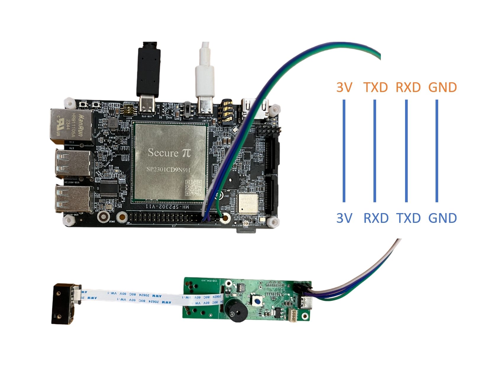
For communicate M104L with SP2302, it is required to use an external board that has layout TTL pins to connect with SP2302.
The following is the pins that is required to connect with SP2302 and M104L

¶ How to use barcode reader in SP2302
1. Install pyserial in SP2302
pip install pyserial2. Clone the demo python codes from our GitHub site.
git clone https://github.com/SecurePi/basic_python_SP2302.git3. Run the python code for barcode reader.
python3 pySerialBarcode.py4. After running the codes, please towards to the extension board and press the button in the middle of the board as follow.

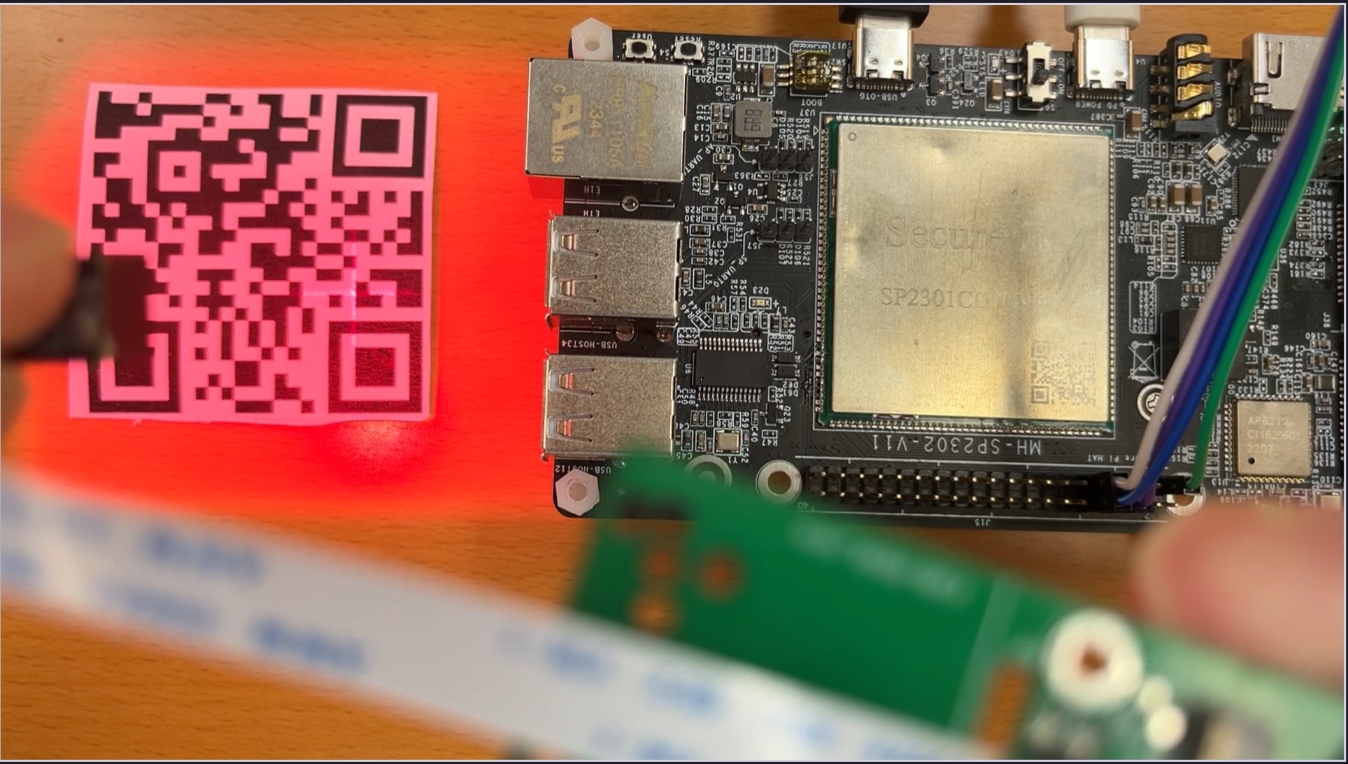
5. The reader will projects the red light for scanning QR or Barcodes. Please put your codes under the red light for scanning as follow.

6. It will show the barcode result in SP2302 as follow.
