¶ Overview
The Secure Pi SP2302 SBC, based on the SP2301 core board, is an advanced single-board computer integrating Apollo Secure MPU with a Linux OS, designed for robust industrial-grade applications. Similar to the Raspberry Pi, it includes a 40-pin header for broad expansion capabilities, 100Mbps Ethernet, WiFi/BLE for versatile connectivity, and multiple interfaces including four USB ports and HDMI output. Ideal for developers seeking a reliable platform for IoT solutions, the SP2302 offers enhanced performance and security, making it perfect for a wide range of applications from automation to Industrial embedded systems.
The SP2302, building on the secure foundation of the Apollo Secure MPU, is tailored to deliver unparalleled security for your industrial development projects. Apollo has passed the rigorous Financial-class PCI PTS 6.X Security certification, significantly reducing the burden and time for achieving compliance for high-standard applications. The SP2302 ensures trusted boot processes through secure boot technology and provides robust protection against physical attack strategies such as Differential Power Analysis (DPA) and Simple Power Analysis (SPA). Additionally, it includes advanced hardware cryptography acceleration, supporting a wide range of algorithms including AES, DES, SHA, RSA and ECC. These features make the SP2302 an exceptionally secure platform, ideal for handling sensitive data and performing secure transactions in any IoT or embedded application.
¶ Specification
- Apollo processor - Cortex-A5 @ up to 1.2GHz+ 32bit RISC Core@up to 200MHz
- Memory: 512MB DDR3L, 512MB NAND Flash
- Wi-Fi and BLE
- 1x USB2.0 Type-C OTG, 5V power supply
- 4x USB2.0 Type-A Host
- 10/100Mbps Ethernet interface
- HDMI interface
- MIPI LCD and CSI interface
- Audio Input and output interface
- Raspberry Pi 40 pin to pin compatible layouts
¶ Document Revision History
| Version | Date | Remarks |
|---|---|---|
| V1.0 | 2024/7/17 | Initial release |
| V1.1 | 2024/9/23 | Added YouTube Video links, GPIO and Buzzer |
¶ Hardware Components in SP2302
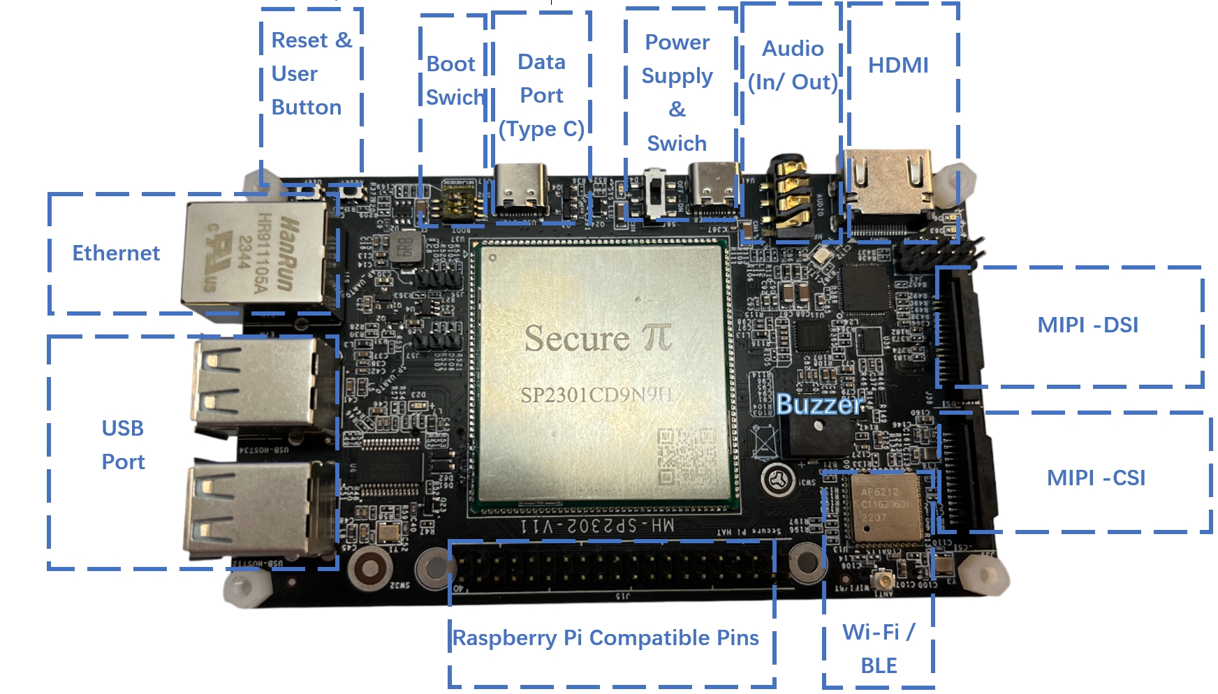
¶ SP2302 front board information
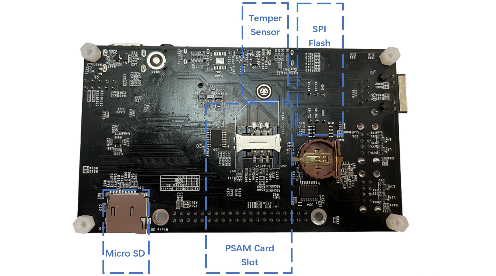
¶ SP2302 back board information
¶ Hardware connection
¶ Power Supply
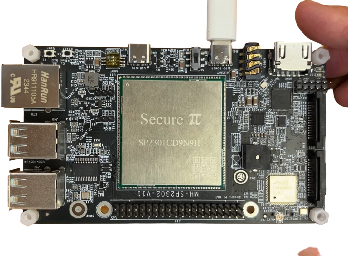
Provide a stable 5V 2A USB to USB Type C power supply to power up SP2302 as follow image.
- Please use external Power supply converter to provide a stable power source.
- For powering SP2302, it is required to turn on the switch next to the power cable.
¶ Insert SD card
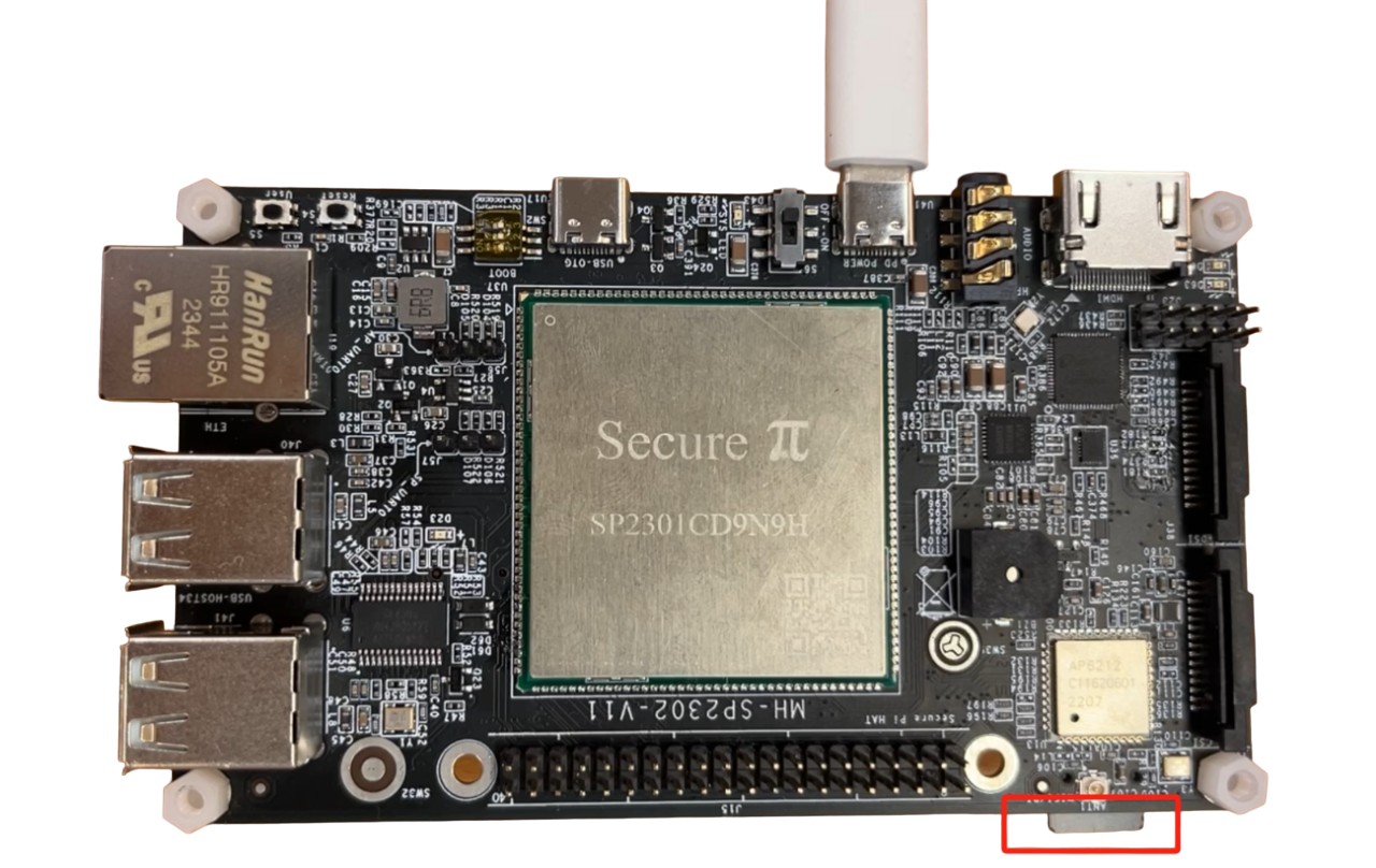
The Micro SD card slot is used for inserting the SP2302 image to power up your Linux OS as follow.
For how to install SP2302 Official Ubuntu image to SD card, please go to Installing Ubuntu image in SP2302.
¶ Data Port
Data Port is the main communication channel for SP2302.
For communication, we need to use a USB to USB type C data cable to connect with a PC and SP2302 Data Port (USB-OTG) as follow.

After connecting the data port, we need to set the boot switch to all Off status to load the image from the SD card.
¶ Ethernet Cable
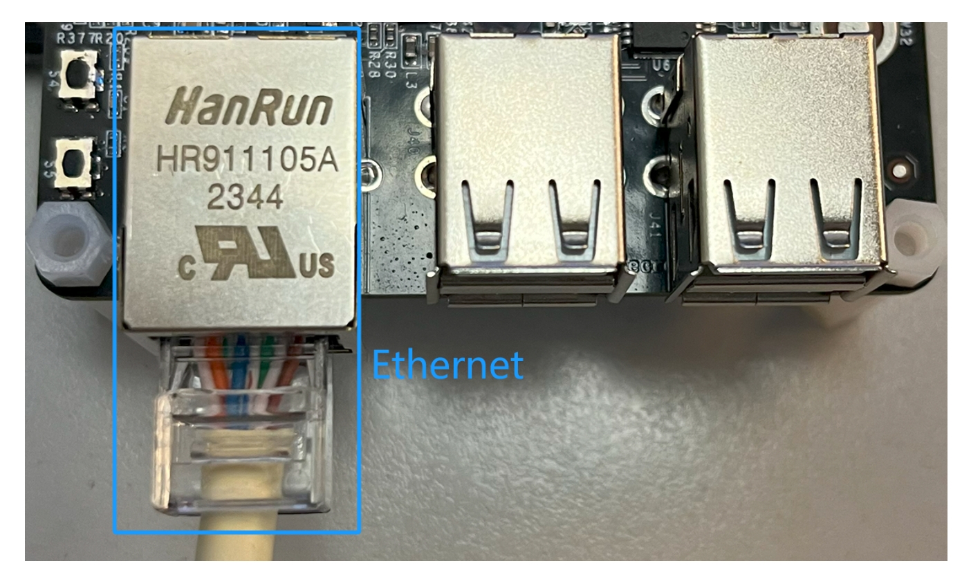
Insert your Ethernet cable to the RJ45 port that located on the Top left corner of the module as follow.
¶ YouTube Video
¶ Activate/ deactivate SP2302
¶ Activate SP2302
For basic hardware connection of SP2302, please refer to Hardware Connection.
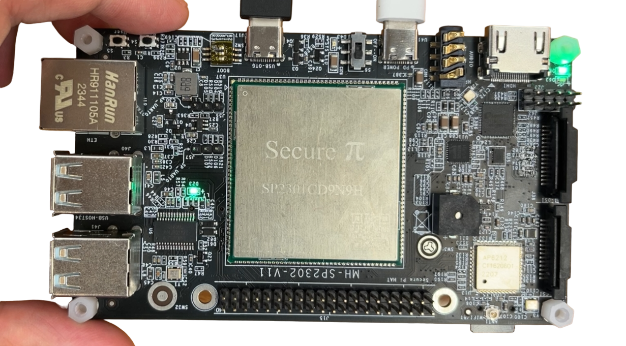
1. Power on the module and press reset button, it will show two led blinks next to the USB port as follow image.
- This means SP2302 is activating the Official Ubuntu OS.
2. Open the PuTTY Serial Terminal and set the as the following.
- Baud Rate: 115200
- Date bit: 8
- Stop bit: 1
- Parity: None
- Flow Control: None
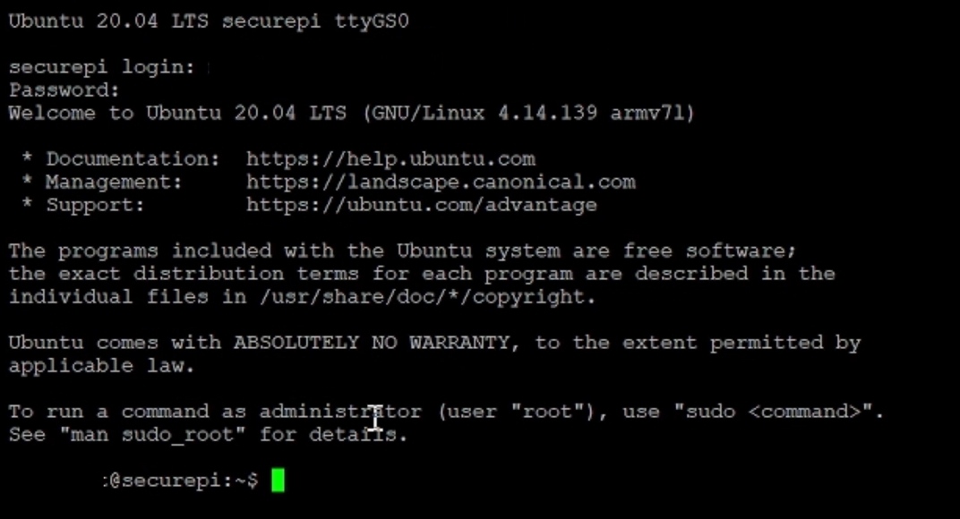
2. Open the terminal and wait until the login section. Type in the following default information to login to SP2302
Username: root
Password: securepi
¶ Deactivate SP2302
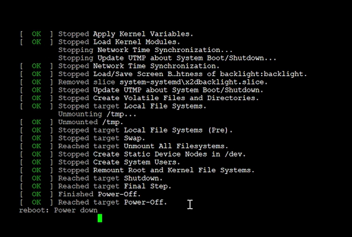
Type in the following command to turn off SP2302 properly.
If SP2302 does not turn off properly, it will easily damage the image in the SD card.
shutdown -h nowor
poweroffAfter entering the commands, please wait until you saw power down as follow.
¶ YouTube Video
¶ Installing Ubuntu image in SP2302
¶ Create an SP2302 SD card image file:
1. Required an Ubuntu OS system as follow.
a) Ubuntu OS 16 / 20 / 22 version
b) GNU awk version: 5.1.0 or above
c) split version: 8.32 or above
2. Upzip the Zip file.
Command: Upzip Secure pi_SP2302_images.zip
3. Please make sure “mksdimage.sh” in the folder
4. Convert to Root mode and input the following command to get the first image file
./mksdimage.sh -i mh_user/programs_sd_7G432M_z_ub.xml -o “name of your output image”
Example for this demo:
./mksdimage.sh -i mh_user/programs_sd_7G432M_z_ub.xml -o sp2302.imgPlease ensure image folder is located with the script in the main folder
The following is the result for creating the first image.
5. Input the next command to the script to create the final version image file
./mksdimage.sh -i mh_user/programs_sd_7G432M_z_ub.xml -f “name of your output image” -m 8 -o “final output image name”
Example for this demo:
./mksdimage.sh -i mh_user/programs_sd_7G432M_z_ub.xml -f sp2302.img -m 8 -o sp2302_final.imgThe following is the result for creating the final image.
6. Compress the image file in xz format.
xz “final output image name”
Example for this demo:
xz sp2302_final.imgThe following is the compressed image
¶ Save the image into SD card
1. Please use Rufus to save the image file into SD card
2. Select the related SD drive and image file
3. Ensure to remove everything from the SD card to allow to install the image.
¶ YouTube Video:
SP2302 SD card image installation
¶ Networking
¶ Activate Ethernet
1. Please connect to your router with internet service with SP2302's Ethernet Port.

2. Go to root file then go to “etc/netplan” and create or modify a yaml file called “01-network-manager-all.yaml”.
Head to the root folder

Towards to “etc/netplan”

Create or modify the “netplan yaml file”

3. In this file, add or modify the following codes and save the file.
Code:
network:
	version: 2
	renderer: NetworkManager
	ethernets:
		eth0:
			dhcp4: true

4. Apply the netplan by "sudo netplan apply".

5. Check the IP has it been activated by using "IP a" command.

6. Ping Google.com

¶ YouTube Video
¶ Activate Wi-Fi
1. Go to root file and head to the same yaml file located in the etc/netplan.
Head to root folder

Towards to “etc/netplan”

Modify netplan yaml file

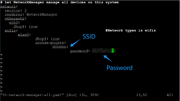
2. Add Wi-Fi settings on the netplan with correct SSID name and password.
Codes:
network:
	version: 2
    renderer: NetworkManager
    ethernets:
    	eth0:
        	dhcp4: true
	wifis:
        wlan0:
        	dhcp4: true
        	access-points:
        		Input SSID name:
        			password: Input SSID Password
3. Apply the netplan by "sudo netplan apply".

4. Check the IP has it been activated by using "IP a" command.

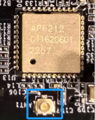
4a) If “wlan0” does not provide an IP address, please check your SSID and password is it correct.
4b) If it is correct, please add an external antenna next to the Wi-Fi module and apply the netplan again.
5. Ping Google.com

¶ YouTube Video
¶ USB port
¶ Activate USB
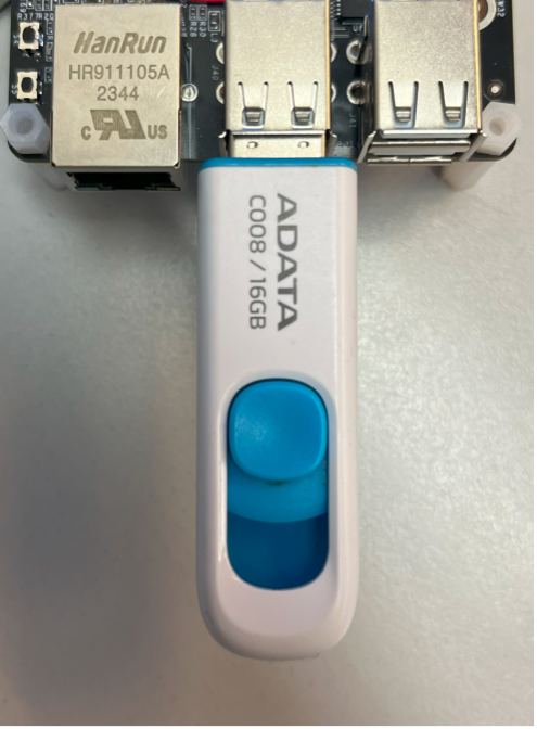
1. Plug in a USB drive in one of the four USB Ports.
2. Search for detail USB information using “fdisk -l”.
2a) Please download “usbutils” before using “fdisk” command.
Command to download: sudo apt install usbutils
Command: sudo fdisk -l

It found the device location is “dev/sda1”.

3. Mount the USB port to mount folder (mnt).
Command: sudo mount -t vfat /dev/sda1 /mnt

4. Go to the root and check the result by go into “mnt” folder.
Towards to the Root file

Towards to “mnt” folder and check the result

It showed the information inside the USB could showed in “mnt” folder.
5. Unmount this USB port.
Command: sudo umount /dev/sda1

6. Eject the USB port.
6a) Please download “eject” before using this command.
Command to download: sudo apt install eject
Command: sudo eject /dev/sda1

7. Check “mnt” folder to make sure the USB has been removed.

¶ YouTube Video
¶ GPIO Pin
For the detail description of GPIO pins of SP2302, please refer to Hardware Development Resources
¶ How to configure GPIO Pins in Python
For configure the GPIO Pins, there are three main steps to make it happen. For details, please refer to our GitHub Site.
1. Please use pip to download the “gpiod” library
Command:
pip install gpiod2. Set the GPIO pins – Selecting the wanted pin to be a GPIO pin and set it as output.
3. Set the GPIO pins - Set the GPIO value (Turn On / Off the GPIO output)
4. Control the GPIO – We need to have a function for configuring the GPIO pins
5. Test the GPIO pin with a LED light blue.
Use git clone command to download the GitHub repository:
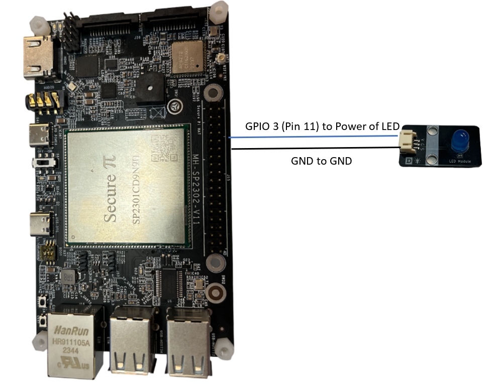
git clone https://github.com/SecurePi/basic_python_SP2302.gita) Testing Environment Setup: We will connect GPIO3 in Pin 11 with the LED. We could check the GPIO status determine by the Light’s status.
b) Python3 with command to Turn on GPIO3:
Command:
python3 gpio_control.py 3 1- Remarks: 3 means GPIO3, 1 means Turn on
- Feedback: GPIO has set to High (Turn on)


c) Python3 with command to Turn off GPIO3:
Command:
python3 gpio_control.py 3 0- Remarks: 3 means GPIO3, 1 means Turn off
- Feedback: GPIO has set to Low (Turn off)


¶ YouTube Video
¶ Buzzer
There is an inboard buzzer in SP2302 for general use. It used internal offsets configuration to control the Buzzer.

¶ How to configure SP2302’s Buzzer in Python:
This Buzzer Python coding has used gpiod library to control one of the offsets in SP2302 that has connected with the buzzer. By controlling this offset, we could control the buzzer. For detail information of this code, please refer to our GitHub Site.
1. This Python coding required to have gpiod library
Command:
pip install gpiod2. For this demo python coding, you need to set the offset through gpiod library
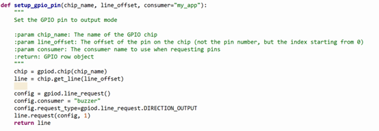
3. For setting the value, you could use the following function to handle it.

4. The main function will provide a demo to control the buzzer with a 1 second delay.

5. Run the buzzer python code:
Use git clone command to download the GitHub repository:
git clone https://github.com/SecurePi/basic_python_SP2302.gitCommand:
python3 buzzer.pyFor having a better understand of the result, please refer to the YouTube Video below.
¶ YouTube Video
¶ UART
For communicate through UART interface, it is required to have the following Hardware requirements.
1. Hardware connection: We need to connect the GPIO pins for UART2's TXD, RXD and GND pins. Please find the following image for details
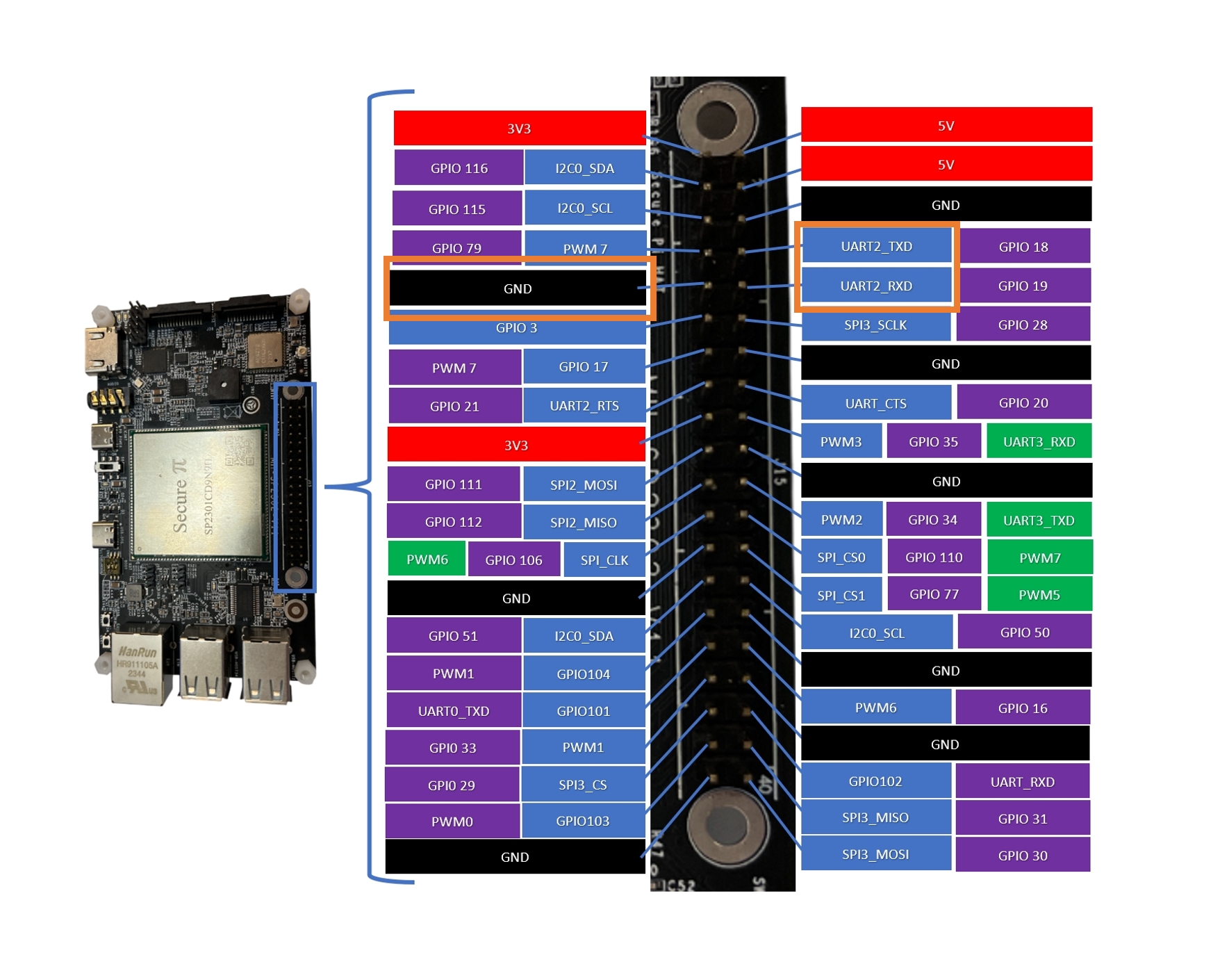
2. If you are communicating with your PC, we recommend you to use a USB to TTL converter.
¶ How to configure SP2302's UART in python
The UART communication python code is a UART loopback code. For details, please refer the following description or towards to our GitHub site.
For activate the SP2302 UART terminal in python , it is required to have a pyserial library.
pip install pyserial1. For our demo code, we will open SP2302's serial port that is /dev/ttyMH2 with 9600 baud rate.
By receiving the data from serial terminal, it will directly return the data back to the sender with printing the result of data in SP2302.
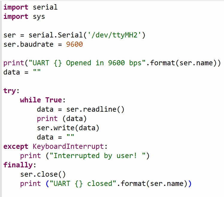
2. Run the codes
Use git clone command to download the GitHub repository:
git clone https://github.com/SecurePi/basic_python_SP2302.gitCommand to run the code
python3 uart.pyFor detail demo, please refer to our YouTube video below.